Hardware design for AVR Microcontrollers
The days when adding a microprocessor meant large amounts of support hardware to provide clocks, reset signals, memory, etc are over.
AVR microcontrollers have integrated RAM & ROM & peripherals. They have optional external reset and clock signals. If these are not used (the default) the clock will be provided by an internal RC oscillator and the reset signal derived from the power rail. An internal circuit will detect switch-on and generate a siutable reset pulse.
Everything about clocks, reset, etc is software configurable but the default will allow programs to run so for undemanding applications the minimum circuit you need is power and a 6 pin ISP header which connects to pins on the microcontroller and allows its flash ROM to be programmed via an AVR Dragon USB JTAG programmer, see software HOWTO page.
For example the AVR88 has different versions which will work with power supplies as follows:
| Microcontroller | Supply | Max Clock speed |
| AVR Atmega88PV | 1.8-5V | 4MHz |
| AVR Atmega88PV | 2.7-5V | 10MHz |
| AVR Atmega88P | 2.7v-5V | 10MHz |
| AVR Atmega88P | 4.5-5.5V | 20MHz |
Note that all versions come in a variety of packages and the 28 pin PDIP package is best to use unless more I/Os or RAM is needed. Available parts are as below. Most embedded controller programs will fit into 16K, but if you need more RAM the larger devices may be necessary.
| Cost | Device | RAM | ROM | Package |
| £1.50 | AtMega88 | 1K | 8K | PDIP28 (0.3") |
| £2.50 | AtMega164 | 1K | 16K | PDIP28 (0.3") |
| £4 | AtMega328 | 2K | 32K | PDIP28 (0.3") limited UK availability March 2009 |
| £5 | AtMega644 | 4K | 64K | PDIP40 (0.6") |
| £15 | AtMega1281 | 8K | 128K | TQFP64 (SMT) Use mounted on 64 pin 0.1" standard square header, see kanda.com |
Clock circuits
The internal RC clock is 10% accurate however it can be trimmed in software to within 1% if a suitable timing source is available. This is not easy, but possible.
A crystal can be connected between two clock pins to provide a high accuracy clock.
If another clock is available it may be connected to an external pin to provide a clock.
The clock speed affects how fast C will run, though normally this is not a problem. It also affects the maximum baud rate of the UART. See datasheet for this, for example with a 4MHz clock baud rates up to 500kBaud are possible, but the highest "standard" baud rate with an acceptable clock error is 38400Baud.
Circuit
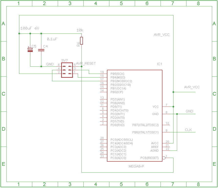
Figure 1 below shows a minimum circuit, from EAGLE files. The header is a 6 way IDC male (can be horizontal or vertical mounting) for connection of an AVR Dragon. AVR_VCC must be supplied at the appropriate voltage versius ground. CLK may be left unconnected if an external clock sugnal is not used. The decoupling accros the power supply is recommended. DC power requirements are minimal but there will be high frequency spikes. Note that all the pins (including CLK) except supplies can be reprogrammed as GPIOs if needed, and that AREF must be decoupled to GND with a capacitor if the ADC is used to minimise noise. RESET can be used as a GPIO but it is more practical to keep it as a RESET input since otherwise ISP flash programming will not work and JTAG programming, the alternative, uses more connections.
Depending on application it may be convenient to add a push button between RESET and ground to allow manual reset of teh circuit separate from the AVR Dragon (which also can reset the circuit). In this case a 0.1uF capacitor between RESET and GND will help remove switch bounce and make the reset signal cleaner. See datasheets for further information.

Figure 1