Note: Some of the graphical elements of this site are only visible to browsers that support accepted web standards. The content of this site is, however, accessible to any browser or Internet device.
Control and Power Portfolio Partnership
CONTROL OF DC/THREE-PHASE POWER CONVERTER
BACKGROUND ON DISTRIBUTED POWER GENERATION
Conventional power stations are often situated in remote locations, where the waste heat they produce may not be effectively utilised. There are also considerable power losses associated with the electrical distribution networks which they employ.
 By contrast, the distributed power generation enables the local generation
of electrical power to minimise power distribution losses and local utilisation
of waste heat to maximise overall thermal efficiency. Waste heat may be
diverted to a boiler that provides hot water and heating for a building
or to a heat exchanger for air conditioning or refrigeration applications.
Gas turbine engines are particularly well suited for these applications
because of the high temperature exhaust heat they produce, unlike conventional
piston engines where the exhaust heat is of a lower temperature.
The concept of distributed power is seen as a major advance in improving electrical power generation efficiency, thus minimising the emissions of greenhouse effect gases and atmospheric pollutants. A significant shift in the orthodoxy of power generation, transmission and distribution is undergoing. The large plants (about 1000 MW) of recent times are no longer being built but small (10 MW) and mini (1 MW) plants are. Instead of being centrally controlled and connected to the transmission grid, they are autonomous and connected to the local distribution network.
Several reasons for this shift are:- co-generation (combined heat and power), which dramatically improves the efficiency of fuel use, is most practicable at small scale;
- generation from renewable sources is more practical on a small scale;
- power converters with large power, high voltage, are available
Why do we need converters?
The new generating technologies do not produce 50Hz AC and thus they need semiconductor-based power converters to connect to the grid. Wind-turbines are most effective if free to generate at variable frequency and so need AC (variable frequency) to DC and then to AC (50Hz) conversion. Small gas-turbine driven generators operate at high frequencies and so they also require AC-DC-AC conversion. Photo-voltaic arrays require DC to AC conversion.
The distribution network has relatively high supply impedances and distortion of both voltage and current waveforms are prevalent because of the many rectifier (non-linear) loads.
The DC-AC power converters consist of semiconductor switching elements and passive components for filtering or short-term energy storage.

The power converters must follow periodic references subject to harmonically related current disturbances from rectifier loads and non-harmonic disturbances due to fluctuating energy input, e.g. support/blade interaction of a wind turbine, or fluctuating energy demand, e.g. cycles of operation of drives in machine tools. The converters are advantageous here because they offer control possibilities not present in conventional generators. In principle, the instantaneous output of the power converter can be controlled to ensure that, despite distortion of the current in the network by some customers, other customers can receive an undistorted supply. Actually, this cannot be achieved with the currently used control techniques: a three point controller does not produce good waveform quality in the presence of nonlinear loading. A controller designed by the dq(synchronous) reference frame transformation of a three-phase system can yield good waveform quality, but only if the system is balanced. Utility companies face large unbalanced loads at the distribution points of their networks and so the transformation is not particularly helpful. Repetitive control offers a much better alternative, as it can deal with a very large number of harmonics simultaneously, and even with several disturbances at different frequencies.
Control theoretic background
For a linear finite-dimensional plant, it is known that the tracking and the disturbance rejection problems are closely related. If the reference and disturbance signals have a simple and known structure (such as constant, linear or sinusoidal with known frequency), then both problems can be solved accurately using the internal model principle, formulated by B. Francis and M. Wonham in the seventies. We are interested here in the more complex class of periodic (or nearly periodic) signals. These are the most frequently encountered signals in engineering (it is this fact which enables the widespread use of oscilloscopes in electronics). They appear as engine noise, voltages and currents in power grids, signals associated with motors, generators, power converters, and other periodic processes.
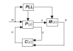
In its original form, repetitive control means the tracking of periodic reference signals using an internal model in the control loop, which is realized by connecting a delay line in a positive feedback loop. This area of control theory was invented in Japan in the eighties (the first application was the control of a particle accelerator). The internal model being now infinite-dimensional, a repetitive control system is difficult to understand and analyse by conventional methods for linear systems. The corresponding theory and design procedures have evolved considerably since the inception of the method. The block diagram of a repetitive control system is shown in the figure below.

Here, the transfer functions P, C and M
represent the plant, the compensator and the internal model. In this diagram,
w is the vector of external signals (references and disturbances),
assumed to be periodic, and e is the error signal which should
be made small. e is the control input of the plant and y
represents the measurements available in addition to e (y
may contain some components of w).The internal model is given by ![]() ,
where W is a rational stable filter with
,
where W is a rational stable filter with ![]() ,
typically a low-pass filter.
,
typically a low-pass filter.
First we discuss the case when the period of w is known. The filter
is such that W(i![]() )
approximately equals one for
)
approximately equals one for ![]() in the relevant frequency range, i.e., in the range where the Fourier
coefficients of w are not negligible. Here,
in the relevant frequency range, i.e., in the range where the Fourier
coefficients of w are not negligible. Here, ![]() >0
is the period of w (actually it is better if it is slightly less).
Such an M can be realized by connecting several delay
lines (according to the dimension of e) in cascade with
W into a feedback loop. There are two technical conditions
required for the closed-loop system to be exponentially stable. We do
not state them here, but we stress that these are standard H-infinity
type conditions not involving M. Thus, efficient algorithms
are available for finding compensators C(s) which satisfy
these conditions (unless the problem is unsolvable, which is rare but
possible). A third technical condition is needed to insure
robustness with respect to small delays in the feedback loop. If the three
technical conditions mentioned above are satisfied, then the repetitive
control system shown in the figure will function and the steady state
error will be very small. (How small depends on how close W(i
>0
is the period of w (actually it is better if it is slightly less).
Such an M can be realized by connecting several delay
lines (according to the dimension of e) in cascade with
W into a feedback loop. There are two technical conditions
required for the closed-loop system to be exponentially stable. We do
not state them here, but we stress that these are standard H-infinity
type conditions not involving M. Thus, efficient algorithms
are available for finding compensators C(s) which satisfy
these conditions (unless the problem is unsolvable, which is rare but
possible). A third technical condition is needed to insure
robustness with respect to small delays in the feedback loop. If the three
technical conditions mentioned above are satisfied, then the repetitive
control system shown in the figure will function and the steady state
error will be very small. (How small depends on how close W(i![]() )
is to 1 for the relevant values of the frequency
)
is to 1 for the relevant values of the frequency ![]() .)
.)
Often we have to deal with references and disturbances which are superpositions of periodic signals (of arbitrary periods), or multi-periodic signals for short. These require a nontrivial extension of repetitive control, but for which detailed studies have not yet been carried out. The need for such an extension is clear in the control of a DC/AC power converter, if the reference voltage is sinusoidal (50 Hz), while the load current is a superposition of periodic components, one at the grid frequency with harmonics due to nonlinear loads and others at lower frequencies due to rotations of machine tools. In addition, the DC supply voltage of the converter may have a high frequency ripple due to a high speed generator. Using an array of internal models tuned to the many individual harmonics of these signals would be impractical as it would lead to numerical problems and lack of robustness. The natural solution seems to be multi-periodic repetitive control.
If the periods of the periodic components of w are not known or may be drifting, then they have to be determined and tracked. This is usually the case, for example the grid frequency or the rotation speed of the turbine-driven generator are slightly changing. Tracking the frequencies can be done by various methods (FFT, correlation analysis) but we think that the most natural devices here are phase locked loops (PLL). The novel problem is that we have to let the different PLL circuits to communicate with each other to prevent them from locking onto the same frequency (probably corresponding to the component with the highest amplitude). Since the technical conditions required for the stability and robustness of the repetitive control system are independent of M , the periods in M can be continually adjusted.
Another related area where the (possibly multi-periodic version of) repetitive control seems promising is active power filters. These create a current composed of harmonics of the grid frequency (but not the fundamental frequency) so that no power is dissipated in the filter, such that the total current consumption of a consumer and filter becomes close to sinusoidal (if the control of the filter is good).