
 .
.
Technical Details
Leaky Cables
One solution that we can use is leaky cable. Leaky cable is a normal coaxial cable, with periodic apertures/slots, for it to emit and receive radio signals. Having this property, it can function as an antenna where it can distribute radio waves at places where the placement of discrete antenna is not feasible (in our case, the LU). Typically, there are a few types of leaky cables , which are determined by the structure of their outer conductors: braided, axial slotted and periodically slotted coaxial cable .
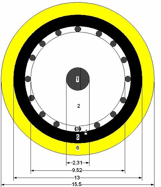
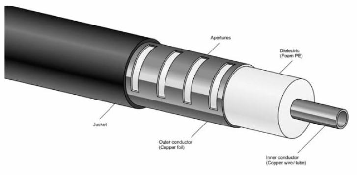
Figure 1: General internal and external (correspondingly) structure of a leaky cable.
Inner conductor is usually made of copper wire. There are several types of dielectric that can be used, depending on the radio wave velocity. Generally it is made of polyethylene with a permittivity about 1.25 , the ratio sufficient for radio wave permeability. The outer conductor, made of copper foil, is the layer at which the arranged apertures are made.
However, the usage of leaky cable is not as easy as it seems. Since Underground stations are further apart, one long leaky cable has to be installed. Otherwise, the radio wave connection between the controller over ground and the mobile phones would fade away as the train moves. Furthermore, there are other main aspects that we have to look into when we deal with leaky cable which are frequency bands and the coupling loss.
As mentioned above, every network provider in the UK has their own frequency range for GSM. The question is 1) How are we going to ensure that, by using this leaky cable, these radio frequencies would not interfere to each other and from other sources? 2) What is the design of the leaky cable that we have to look into to overcome this problem?
Another problem is coupling loss. Coupling loss can be defined as the ratio between the power received by the half-wavelength dipole antenna and the transmitted power in the cable8. How are we going to guarantee that when the wave is radiated from one medium to the other, there would not be significant losses in power that would disrupt the connection? These are the things that we are trying to solve and hopefully would be able to reach to a solid conclusion.
Technicality of Leaky Cable
In this part, periodically-slotted coaxial cable is analysed theoretically in more detail including equations and explanations. We will discuss the properties of the slotted coaxial cable, including the basic principle of frequency bandwidth expansion, coupling characteristic and the field distribution. All these important parameters will help us understand how exactly the leaky coaxial cable propagates the signal in the underground telecommunications system.
As we have discussed before, the signals transmitted and distributed in the leaky coaxial cable are in the ultra-high frequency wave range (from 300MHz - 3GHz) and travel at the speed of light. Unlike the usual coaxial cable, the leaky coaxial cable implemented in the underground tunnel does not only work as a normal cable but also functions as an antenna in the tunnel. Based on the theory of the ray diffraction, each slot of the radiating cable can work as an antenna spreading the signal out in the tunnel.
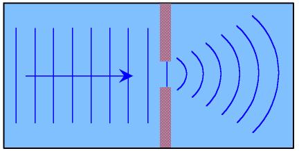
Figure 2: Radio waves will behave as the picture when they pass through the slots.
Field distribution
Since each dimension of the slot is relatively smaller than the wavelength of the frequency, the radiation of the signal can be consider as a magnetic dipole in the free space .Therefore the leaky cable will behave as long arrays of the magnetic dipoles. By letting k*d*cos? - ßg *d= 2n? (n is any integer), we can find out at which angle we can get the maximum total electric field and the radiation pattern of different angles. Therefore, by this equation we can find out where to place our leaky cable to maximise the signal.
Coupling characteristic
Coupling loss is the loss of energy when transferred from a circuit to another. In this context, it refers to the energy distribution between the cable inside the slots and the space outside the slots.
The coupling loss varies along the cable; it depends on the period of the slots, the slots number in each period, (with or without the radiation of high harmonics), and the different inclined slotted angle. Based on previous research , it is noted that the higher the period of the slots, the larger the coupling loss would be while suppressing out the high order harmonics will stabilise and flatten the coupling loss (which is what we want) in comparison to the cable with the high order harmonics. Furthermore, as the inclined slotted angle increases, the coupling loss will increase as well. From these, we can conclude that for a leaky cable to act as a better antenna, it would have high periodic slots at an inclined angle.
General Implementation of The Whole System in the Underground
We have mainly talked about leaky cable previously. Now we are going to merge it with the whole system so that the signals from the base stations can be sent to the mobile phones in tunnel back and forth. Nowadays we generally have two types of technology for mobile networks in the world:
1.GSM( Global System for Mobile Communications)
2.CDMA (Code division Multiple Access) - A form of multiplexing, which is one transmission channel being used to allow a number of signals to pass through. Applied in 2G and 3G technology.
In the UK, both are these are used in the mobile network. However the frequency band of CDMA is very close to the GSM900. These two systems may interfere with each other particularly between the downlink of CDMA (870-880MHz) and the upper link of GSM (890-915MHz) . The distribution system consists of leaky cables, transmission lines, Point of Interconnection (POI) platform and Low Noise Amplifiers (LNA). The POI platform consists of couplers, filters combiners and splitters. The function of POI is basically to combine multi-band signals and to eliminate the inter-system interference. For the downlink operation, POI combines multiple signals while for the upper link, it divides the mixed signals from the leaky cables into signals in different bands.
In order to ensure that the signals are strong enough to reach mobile phones underground, we need to amplify the signals. So, amplifiers can be placed before passing them to POI. A variety of signals from both GSM and CDMA will be filtered into POI platform from base transceiver stations before being sent to leaky cables. The signals will be first split and then routed to POI platform which are placed in stations, and tunnels.
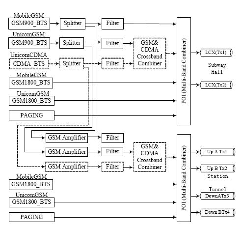
Figure 3:Down link of the system
For the upper link, POI platform will divide mixed signals from leaky cables into different frequency band. The signals are then filtered and sent to the corresponding base transceiver stations. This division function is convenient to make different systems share a common leaky cable so that the cost of leaky cables is reduced14.
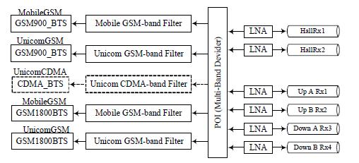
Figure 4: Upper link of the system
COST
According to communications requirements of subway train control system and the characteristic of leakage wave communications, 2 leaky coaxial cables are required for the communications between left-going train and right-going train respectively. As leaky coaxial cables are required to be installed on both sides of the railway, the total length of leakage cable is twice as long as the railway. In the meantime, receivers and in-train receivers are also required . However, the main cost of communications lies on the leakage cables .
On the other hand, the power consumed in communications is weak current, and the total weak current consumption only takes up 2% of the total power consumption in the subway system. Therefore the power consumption cost could be ignored as compared to other parts .
In choosing the specification of leaky coaxial cables, the construction environmental factor, equipment parameters and system expansion requirements should all be taken into consideration. The price of radiated leaky coaxial cables for underground communications system is around US$1,000-US$10,000 per kilometer. Taking other communications charge into consideration, the communications cost for each meter in tunnel is within US$2,000-US$20,000. Therefore, Piccadilly Line (76 KM) needs at least US$152,000-US$1,520,000 .
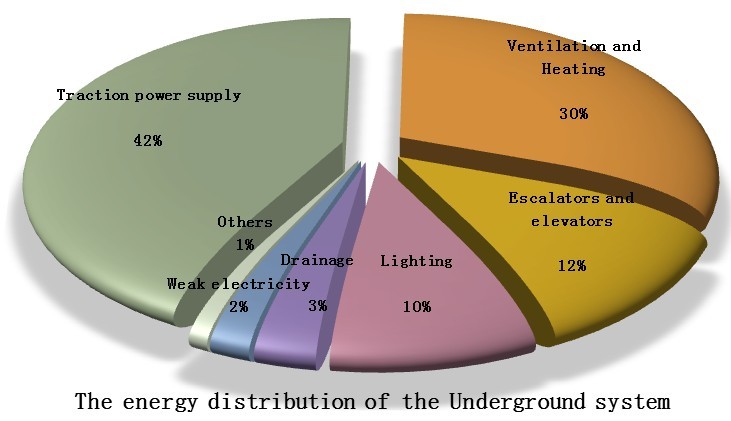
Figure 5: The energy distribution of the Underground system.
Site Info
© 2011 [Ka Yin]™