HVDC Circuit Breakers
Home | About | Technologies | Report Download | Contact Us
Technologies > Solid State Circuit Breakers
In the above diagrams as we can see the maximum current in solid-state circuit breaker has almost no dependence on the grid voltage and at the same time the higher the voltage the lower the turn-off time.

Figure 3: Solid State Circuit Breaker
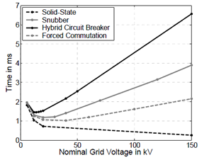
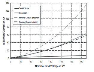
Figure 4: Grid Voltage vs. Time Figure 5: Grid Voltage vs. Maximum Current
|
Voltage |
Solid-State |
Mechanical with Snubber circuit |
Conventional Hybrid |
Forced Commutation |
|
6kV |
6000 |
5400 |
8100 |
11400 |
|
12kV |
9000 |
8800 |
27500 |
21200 |
|
20kV |
21000 |
18000 |
47500 |
34800 |
|
150kV |
300000 |
4450000 |
54544000 |
2602000 |
Figure 6: Cost comparison for four different circuit breaker models
The solid-state circuit breaker model has many advantages compared to
the rest of the circuit breaker topologies. First of all, because of the lack of
any mechanical components the solid-state circuit breaker is much more responsive,
which leads to a reduced turn-off time. Furthermore, the higher the voltage across
the inductor the higher the overvoltage which allows the demagnetization process
to be performed faster as we can see on figure 4. This fast turn-off process limits
the peak current to low levels compared to the rest of the circuit breaker topologies.
Hence, for the same grid voltage the power losses per circuit breaker are very low
in the solid-state case.
With all this in mind, one would assume that the solid-state circuit
breaker is the better choice due to the low component cost, low turn off time and
low peak current regardless of grid voltage or cable length. This however is not
the case because of one significant disadvantage; the high on-state losses. As we
can conclude from figures 4, 5 for low to medium grid voltages the low turn-off
time and low peak voltage are not low enough to counter the power losses during
the on-state. In high voltage grids however, the solid-state topology has an advantage
since the power saved per circuit break is sufficient to make them more economic
compared to the other circuit breakers, even when the on-state losses are taken
into consideration.