HVDC Circuit Breakers
Home | About | Technologies | Report Download | Contact Us
Technologies > Solid State Breaker Simulation
We decided to simulate a solid state circuit breaker using an HVDC model
provided by MATLAB. The model represents a point to point VSC based transmission
at 230kV. In our attempt to simulate the fault, both cables were connected to a
switch, which when opened both cables became grounded. Our breaker consists of an
IGBT and a varistor in parallel. The IGBT is used instead of a GCT because that
was available from MATLAB and their difference is only on the on state losses. The
model is presented below.

Figure 7:
HVDC MATLAB model
At first we tested the power changes when the fault occurred. The fault occurred at 0.3s while the IGBT interrupted at 0.5s. From figure 8 we can see that even though power should be zero, during 0.1-0.3s there are some on state losses due to the use of IGBTs. Furthermore, once the DC fault occurs power increases rapidly, which is normal since current increases until the interruption occurs. Power though continues to oscillate even after the interruption has occurred.
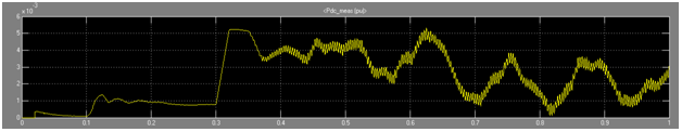
Figure 8: Power vs. time graph
Our simulation showed that solid-state circuit breakers have rather high
on-state losses which can be a clear disadvantage. On the other hand, it
has a very
small interruption time and its functionality at 230kV is very promising.
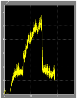
Figure 9: Current vs. Time