
Note: Some of the graphical elements of this site are only visible to browsers that support accepted web standards. The content of this site is, however, accessible to any browser or Internet device.
Control and Power Portfolio Partnership
Fuel Cells in Small-Scale Distributed Generation Systems
STRUCTURE OF THE PROJECT
This project involves several aspects: the definition of the SOFC fundamental specifications based on economic grounds, the modelling and performance of the fuel cell, the design of the power conditioning unit and the implementation of the most appropiate control strategy.
The Control and Power Research Group is involved in all these aspects to some extent; however, this group puts significant more emphasis and effort where its inherent habilities and interests are: in the design of power converter and the development of a suitable control scheme.
Fundamental design based on economic grounds
The best design of a SOFC-based system depends on the particular application under consideration. Several scenarios are being defined in this project: from an industrial application of several hundred kilowatts to a house-hold application of few kilowatts. The latter scenario is being explored first.
The size and most general specifications of a SOFC are being obtained from an economical analysis on a domestic load profile. This analysis involves a formal optimisation formulation. For further information about this aspect of the project search for Dr. Matthew A. Leach and Mr. Adam Hawkes in the Department of Environmental Science and Technology (DEST) at Imperial College.
Figure 1 shows how the profile of the energy demanded to the grid by a typical British house might change if a fuel cell is installed as a complementary power supply. The upper line corresponds to the house energy demand (with some averaging) and the lower trace represents the energy that would be imported from the grid once the cell is installed. The difference between these two curves is the energy the SOFC produces, which has been determined by cost-optimisation procedures. These results also suggest that the best power rating for the fuel cell is the base load.
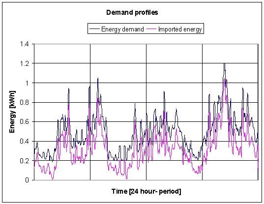
Figure 1. Domestic load profile (data kindly provided by BRE)
Modelling and Performance
Figure 2 illustrates the operating principle of a SOFC. The fuel cell design and its finite differences model is under development. A reduced version of this model, suitable for real-time control systems, is also under construction. To know about more about Solid Oxide Fuel Cells Modelling search for Dr. Nigel Brandon and Dr. Patricia Aguiar in the Chemical Engineering Department at Imperial College.
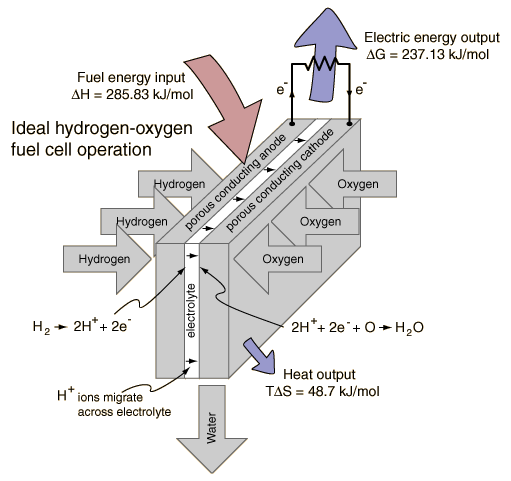
Figure 2. Fuel cell operating principle
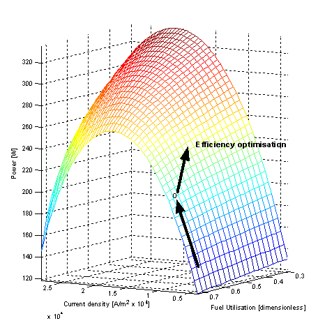
The performance of a SOFC may be optimised for several aspects, such as maximising the output voltage, minimising the current density or minimising the use of fuel. Figure 3 shows the output power capability of the SOFC under design plotted against current density and fuel-utilisation. The arrows show how the fuel utilisation should be controlled to obtain the maximum efficiency from the SOFC at a required power. The change in direction in the fuel utilisation corresponds to the operating conditions where the potential difference between the anode and cathode of the fuel cell (not shown) reaches the minimum value allowed for the safe operation of the cell.
Power converter
The power conditioning requirements of a fuel-cell represents an opportunity to optimise the design of a power converter. This power converter must be able to step-up the DC voltage provided by the SOFC, convert it to an AC waveform and synchronise it with the grid. Figure 4 shows a candidate circuit (based a boost converter) to fulfill such power conditioning requirements. The definite topology to be used is still under analysis. Cost, reliability and power density are top priorities for the hardware design.
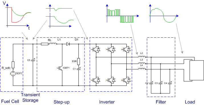
Figure 4. Power converter
Control strategy
A control strategy of a SOFC (depicted in figure 5) must be able to operate the power converter in both, voltage and current control modes without overlooking the qualitu of the delivered power. The control strategy must also assure the safe operation of the SOFC by controlling its temperature, the electrical potential across the anode and cathode of the fuel-cell, and the amount and the rate of change of the output current.
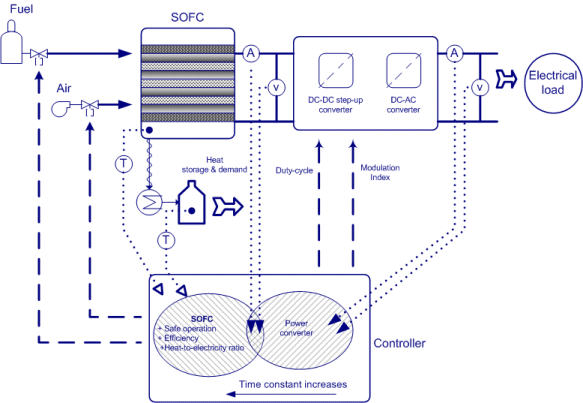
Figure 5. Control scheme for a SOFC
As well as taking care of the technical aspect of the SOFC, the controller must follow a higher level control policy to minimise the running costs of the system. This policy is being developed considering the variable costs of importing and exporting energy from the grid. This is an on going research that will include the time-varying price of the electricity in the market during a 24-hour span.