


Ion Drives
Introduction
Ion drives produce thrust by emitting beams of ions—by Newton’s 3rd law of action and reaction. There are various methods of accelerating the ions but generally all designs have the advantage of a large fuel charge to mass ratio. This means that high exhaust velocities can be created by a small potential difference. Hence, less fuel mass is required.
As such, ion drives are not suitable for use on Earth. Instead, they should be used in space, where their ability to maintain a low thrust for long periods of time will come in handy. For example, they are currently used for orbital manoeuvring and station keeping. There are 3 main types of ion thrusts: electrostatic, electromagnetic and electrothermal. In this section, we will focus on the first two, since electrothermal drives are not really unconventional.
Electrostatic Ion Thrusters
Concept of Operation
Propellant atoms are first ionised by electrons, forming ions in the propulsion chamber. This process is usually performed by bombarding the propellant atoms with electrons. This causes them to lose their own electrons to form positive ions. The lost electrons are absorbed by the thruster grid/wall.
Positive ions diffuse into a plasma sheath. Once in the plasma sheath, the ions experience an electric field between the positive and negative grids (at the exit of the chamber). The electric force, proportional to the charge of the ion and the magnitude of the electric field, will accelerate the ion towards the exit with acceleration proportional to the electric force and the mass of the ion.
At the exit, the ions are focused onto the narrow apertures of the negative grid and shot out in space at high velocities. By Newton’s 3rd law, the force on the ion causes an equal and opposite reaction to act on the thruster/spacecraft. To ensure the net charge neutrality of the spacecraft, electrons are shot out from a cathode towards the ions behind the spacecraft as well.
Types of Electrostatic Ion Thrusters
There are 2 main types of electrostatic ion thrusters; the gridded ion thruster and the field emission electric propulsion/colloid thruster.
The gridded ion thruster was the earliest type of electrostatic ion thruster. Further study into similar concepts to improve efficiency resulted in the idea of the field emission electric propulsion/colloid thruster. Gridded ion thrusters are mainly used for the propulsion of spacecraft while field emission electric propulsion thrusters provide very small levels of thrust which allow for more precise control of spacecraft. A colloid thruster provides an even lower level of thrust which makes it ideal for extremely precise spacecraft control.
Gridded Ion Thruster
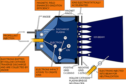
Diagram of a typical gridded ion thruster, the NSTAR
The typical gridded ion thruster is the Kaufman type. Its operation can be divided into ionisation, acceleration, and neutralisation.
Ionisation: Xenon is most commonly used as the propellant. Xenon propellant is first injected into the ionisation chamber’s plasma where it is ionised by electron bombardment from the hollow cathode. Electrons colliding with the xenon atoms cause it to lose one electron per atom to form positive xenon ions. Electron bombardment can be achieved by various methods. The first method is direct current discharge in which electrons flow back from cathode to anode. (e.g. Kaufman type). The second method is radio frequency discharge where electrons are held circulating in an electromagnetic radio wave field (e.g. Radio frequency Ion Thruster, RIT). The last method is electron cyclotron resonance in which electrons are excited by microwaves circling around an electromagnetic field (e.g. Mu and High Power Electric Propulsion (HiPEP) thrusters). The xenon ions are then extracted from the ionisation chamber through a multi-aperture grid extraction system by diffusion.
Acceleration: Xenon ions enter the grid system (in between the positive and negative grid). The potential difference of up to 1,280 V between the positive (screen) and negative (accelerator) molybdenum grid creates an electric field that accelerates the ions out of the exhaust at over 100,000 km/h. Ion energy typically reaches 1–2 keV for the NSTAR. The reaction force of this jet of ion stream out of the exhaust of the engine generates the thrust of the engine.
Neutralisation: In order to prevent the spacecraft from gaining a net negative charge due to the efflux of positive ions, a cathode neutraliser injects electrons into the exhaust to neutralise the positive xenon ions.
Field Emission Electric Propulsion/Colloid Thrusters
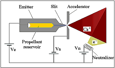
Diagram of Field Emission Electric Propulsion thruster, FEEP
The Field Emission Electric Propulsion thruster (FEEP) is similar in principle to a gridded ion thruster. In the case of FEEP, the propellant used is liquid (usually caesium or indium due to their low ionisation energies, low melting points and high mass). The metal is directly extracted as a liquid in the emitter module through a tungsten needle/slit of about 1 μm.
The propellant flows through this slit and forms a free surface at the exit of the slit. With the emitter acting as a positive grid and the accelerator plate acting as a negative grid, an electric field is established. The surface of the propellant liquid metal at the tip of the needle approaches a condition of local instability due to surface tension and the electric field. A series of protruding cusps of liquid, known as "Taylor cones" are created.
Once the electric field reaches the threshold of 109 V/nm, the metal atoms at the tip ionise and flow out of the accelerator, leaving electrons behind. This results in a jet of ion stream which produces the thrust. Similarly, the neutraliser removes the net negative charge on the engine by emitting electrons.
Colloid thrusters are, in principle, similar to FEEP. They are designed to give smaller specific impulses and thrust for more precise control of force.
Applications
Gridded ion thrusters are already in use in many space operations as a propulsion method. The NSTAR ion engine, on NASA’s Deep Space 1, has travelled more than 28 million miles from Earth as of February 1999. The Xenon Ion Propulsion System (XIPS), developed and used by Hughes Aircraft Company, is now keeping more than 100 geosynchronous satellites flying. Similarly, the RIT, Mu and HiPEP thrusters have been tested or are already in use. Recent advancements include the DS4G, still in the development stage, for which theoretical calculations are promising.
FEEP and colloid thrusters are already in use in many space operations as a precision control method. The Colloid Thruster System developed for JPL Space Technology 7 mission is the precursor for another larger scaled mission called the Laser Interferometer Space Antenna (LISA). 12 FEEP thrusters would be mounted on the hull of LISA Pathfinder to achieve 100 times more accurate control than normal spacecraft.
Electromagnetic Ion Thrusters
Concept of Operation
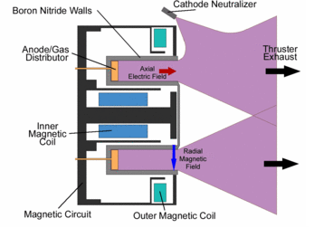
Figure 1: Cross-section of a Hall Effect thruster
These drives work on a similar principle to the electrostatic ones. The main difference is that now, the ions are accelerated by the Lorentz force due to the interaction of a magnetic field and moving electrons instead of the Coulomb force. We will use two examples below to elucidate how these thrusters generally work. There are several types of electromagnetic ion drives. The most popular one is the Hall Effect Thruster. Other types include the Electrodeless Plasma Thruster, the Magnetoplasmadynamic (MPD) Thruster and the Pulsed Inductive Thruster (PIT). The MPD ionises propellant gases like hydrogen or nitrogen into plasma and then accelerates them in a magnetic field. On the other hand, the PIT uses pulses of thrust from a propellant gas which is emitted from a cone-shaped tube.
Hall Effect Thrusters
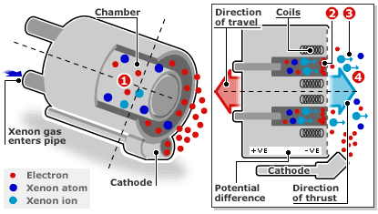
Figure 2: Operation of a Hall Effect thruster
Electrons are generated from the cathode as seen on the diagram on the right. The anode is charged up and the electrons accelerate towards it, from right to left. A radial magnetic field is created between an inner magnetic pole and an outer magnetic ring. This field interacts with the moving electrons, producing a force which stops them from accelerating toward the anode, making them spiral near the exit plane. This direction of flow of electrons is given by E×B, which means it is perpendicular to both the magnetic field and electrostatic current. The propellant used is xenon gas. It is a suitable choice as it is inert and removes the risk of explosion due to a chemical reaction.
Figure 1 shows how the anode duals up as a gas distributor. As the xenon atoms leave the anode and diffuse through the chamber, they collide with the electrons present. Hence, xenon ions are created. Now, referring to Figure 2, we can see that an electrostatic potential has been set up between the positive channel and the negative spiral of electrons. These ions now start accelerating toward the negative end and attain speeds of up to 15,000 m/s. The magnetic field present is such that it is strong enough to cause the light electrons to spiral, but too weak to have any significant effect on the accelerating heavy xenon ions. As the ions exit, an equal number of electrons leave the chamber as well. This process results in the thruster exhaust and enables charge neutrality to be held. Again, charge neutrality is important as it prevents equipment damage.
Electrodeless Plasma Thrusters
Propellant, which must be in a gaseous state, will be inserted in the upstream direction. It is then ionised by various methods, including using an alternating electric field via an inductive or capacitive discharge and using electromagnetic waves. The dense plasma diffuses into a chamber where there is an oscillating electric and magnetic field. The interaction between the plasma and the induced fields leads to propellant plasma being accelerated by the ponderomotive force (non-linear force that occurs in an oscillating electromagnetic field).
This force causes both the electrons and ions to flow in the same direction, in a double layer (a "double layer" has two streams alongside each other with opposite charges). The advantage of this is that it does not need any neutraliser, as the charges already cancel each other out. In addition, it overcomes the erosion and lifetime problems that occur in both the Hall Effect thrusters and gridded ion thrusters as there is no contact between the plasma and any electrodes. However, although practical research on this technology has begun, the theory around the existence of a double layer has been much debated on. Much more work needs to be done before it can be considered a viable rocket drive.
Applications
Hall Effect thrusters have already been developed and used in some space operations. Two main types of thrusters have been developed, the Stationary Plasma Thruster (SPT) and the Anode Layer Thruster (ALT), also known as the Thruster with Anode Layer (TAL). In 2002, the Glenn Research Center in the USA announced that they had built and tested a new Hall Effect thruster, the "NASA-457M", which was apparently up to ten times as powerful as its peers. The European Space Agency (ESA) used Hall Effect thrusters for their SMART-1 Propulsion system in 2003.
Electrodeless plasma thrusters have been developed and tested by The Elwing Company, and are being tested for spacecraft propulsion. The Princeton Plasma Research Laboratory has also begun testing its underlying theory.
Comparison
Comparison between Electrostatic and Electromagnetic Drives
The principle operation of both the families of drives differs in one main aspect—the method used to accelerate ions.
The MPD, an electromagnetic ion drive, is currently the most powerful form of electromagnetic propulsion and can produce up to three times the specific impulse produced by electrostatic ion drives. Hall Effect thrusters also have an advantage over gridded ion drives as they can be scaled up easily (since they have no grids), provide more thrust and use a wider variety of propellants. However, they are usually less efficient.
Comparison with Conventional Rockets
In this section, Ion drives are compared with one of the most powerful conventional rocket engines, the J-2X used by NASA Saturn V spacecraft. There are several advantages:
Higher specific impulse/efficiency
Ion drives have a much higher specific impulse as compared to conventional rocket drives. This means that the impulse per unit mass of propellant is higher and hence much less fuel is required to be carried onboard the spacecraft, making it lighter and more efficient. Operating costs are also much reduced as a result.
Lower thrust
Ion drives are capable of producing thrust in the range of micronewtons. This makes ion drives ideal for control and stability of spacecraft in space missions. However, having lower thrust also means that they cannot be used as an effective launch mechanism as millions of these engines would be required to generate a thrust comparable to that of a chemical rocket thruster. Overall, we see that electrostatic ion drives are better used for spacecraft propulsion and control than launch.
Future of Ion Drives
Due to their much higher efficiency, ion drives are beginning to replace conventional methods of space propulsion. Many geo-satellites running on ion drives can last longer and save on energy consumption and launch costs. Many spacecrafts such as the NASA Dawn spacecraft and JIMO spacecraft are using ion drives as their main propulsion mechanism. More will follow. Research on ion drives in the future mainly aims to utilise new power sources, such as nuclear sources, to develop higher power ion drive thrusters with greater speed and thrust. Carbon-based ion optics and electron cyclotron resonance technologies will increase the lifetime of ion drive engines and allow longer space operations. Ion drives may hold the key for further space exploration.
Space characteristics of various electrostatic and electromagnetic ion drives
Bibliography
- "Electric Propulsion" Wikipedia <http://en.wikipedia.org/wiki/Electric_propulsion>
- "NSTAR Ion Engine" Boeing <http://www.boeing.com/defense-space/space/bss/factsheets/xips/nstar/ionengine.html>
- "Electrostatic Ion Thruster" Wikipedia <http://en.wikipedia.org/wiki/Electrostatic_ion_thruster>
- Butterworth-Hayes, Philip. "Ion Propulsion Concepts". Aerospace America March 2006. Reston, America March 2006. <http://www.aiaa.org/aerospace/images/articleimages/pdf/aa_mar06_ib.pdf>
- "Electrostatic Ion Thrusters" Encyclopedia Beta. <http://en.allexperts.com/e/e/el/electrostatic_ion_thruster.htm>
- "Ion Propulsion in Deep Space 1". Science at NASA. <http://science.nasa.gov/newhome/headlines/prop06apr99_2.htm>
- "Radio Frequency Ion Thruster" EADS Astrium <http://cs.astrium.eads.net/sp/SpacecraftPropulsion/Rita/RIT-22.html>
- E.Foster, John. "Hi-PEP Ion Thruster". NASA Publication. September 2004. Cleveland Ohio. Pp 6 <http://gltrs.grc.nasa.gov/reports/2004/TM-2004-213194.pdf>
- Walker, Roger. "ESA and ANU makes propulsion breakthrough". European Star Agency News 11 January 2006. <http://www.esa.int/esaCP/SEMOSTG23IE_index_0.html>
- "NSTAR Ion Thruster" Glenn Research Center Website. <http://www.grc.nasa.gov/WWW/ion/past/90s/nstar.htm>
- Blandino, John. "Electric Propulsion" Propulsion and Energy. Aerospace America December 2003. Reston, America December 2003. <http://www.aiaa.org/pdf/inside/03_TC_Highlights/aiaa-ep.pdf>
- D.M. Goebel and I. Katz, "Fundamentals of Electric Propulsion Ion and Hall Thrusters", John Wiley & Sons, NY 2008. Chapter 9. <http://descanso.jpl.nasa.gov/SciTechBook/series1/Goebel_09_Chap9_Flight.pdf>
- "Field Emission Electric Propulsion". Alta-space website. <http://www.alta-space.com/index.php?page=feep>
- "FEEP and Colloid Thrusters" Non-equilibirum Gas and Plasma Dynamics Laboratory. <http://mnemosyne.engin.umich.edu/electric-propulsion/field-emission-electric-propulsion>
- M.Marrese, Colleen. "Electric Propulsion Applications for Field Emitter Cathodes" Jet Propulsion Laboratory. Pasadena, CA. <http://trs-new.jpl.nasa.gov/dspace/bitstream/2014/15002/1/00-1003.pdf>
- "J-2X engine" Pratt & Whitney. <http://www.nasa.gov/pdf/214593main_Bouley(Lamm)2-26-08.pdf>
- "Ion Propulsion" Wikipedia <http://en.wikipedia.org/wiki/Ion_thruster>
- "Advanced Propulsion Concepts". The Internet Encyclopedia of Science. <http://www.daviddarling.info/encyclopedia/H/Halleffectthruster.html>
- Emsellem, G. "Electrodeless Plasma Thruster Design Characteristics and Performances". 4th International Spacecraft Propulsion Conference (ESA SP-555). 2-9 June, 2004. <http://adsabs.harvard.edu/abs/2004sppr.confE.124E>
- Greg Goebel. "Advanced Space Rocket Propulsion Systems". IN THE PUBLIC DOMAIN. chapter 3 of 7. 01 June 08. <http://www.vectorsite.net/tarokt_3.html#m1>
- European Space Agency. "Electric Spacecraft Propulsion : Smart 1 Propulsion System" <http://sci.esa.int/science-e/www/object/index.cfm?fobjectid=34201&fbodylongid=1539>
- The Elwing Company. <http://www.elwingcorp.com/>
- Robert H. Frisbee and Ioannis G. Mikellides. "The Nuclear-Electric Pulsed Inductive Thruster (NuPIT): Mission Analysis for Prometheus". California Institute of Technology. <http://www.grc.nasa.gov/WWW/InSpace/pubs/propcon05/NuPIT_NEP_Mission5_(Frisbee).pdf>
- Glenn Research Center. "Magnetoplasmadynamic Thrusters". NASA. <http://www.nasa.gov/centers/glenn/about/fs22grc.html>